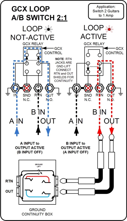
Here is a dwg that I put together to explain how the GCX relays can be configured as...
FX LOOPS
A/B Switch (2 Inputs to 1 Output)(Switch 2 guitars to 1 Amp)
A/B Switch (1 Input to 2 Outputs)(Switch 1 guitar to 2 Amps)
Normally Closed Amp Switch
Normally Open Amp Switch
It helps explain what's going on inside the powerful GCX
enjoy
Joe
GCX CONFIGURATION DRAWINGS
-
- Posts: 75
- Joined: Fri Jan 27, 2012 8:32 am
- Location: Toronto, Ontario, CANADA
Re: GCX CONFIGURATION DRAWINGS
Absolutely no offense intended here, Joe, because I know we discussed this in another thread just last week, but I have to reiterate that, while the signal routing in your first example [A/B Switch 2:1] does work, I fear anyone using a GCX will find it more confusing than anything else.
Your diagram shows the connection of the two Input signals to the Out and Send jacks and the loop's output coming from its In jack, whereas the logical connections to make in this scenario are to connect the two input signals, whether they be two guitars, two FX unit returns or even two preamp outs, to the In and Return jacks of the GCX Loop so the active signal will be routed to the Out jack. I believe this will make a lot more sense to users because, for all intents and purposes, the signals will be traveling in the "correct" direction as opposed to traveling "backwards," and by backwards I mean connecting an Input signal to an Output jack and getting an Output signal from an Input jack.
For Sale: Original DMC GCX in Excellent Condition ($275) and a far more versatile SoundSculpture GL also in Excellent Condition ($1750). Free CONUS Shipping.
-
- Posts: 75
- Joined: Fri Jan 27, 2012 8:32 am
- Location: Toronto, Ontario, CANADA
Re: GCX CONFIGURATION DRAWINGS
Hi nyteowl,
Thanks for the comments, but as I mentioned in the other thread, you can use the ins as outs and the outs as ins, with no possibility of damage, since the relay is completely Passive and is not directional...the 2:1 configuration is useful if you want to switch 2 guitars (or other instruments) to one amp.
There should be no fear because if you don't understand it, and connect it wrong, there will be no audio!
The reason I made the drawings was to educate by explaining how the signals flow through the GCX relays...
Although novice users will probably not take advantage of the 1:2 and 2:1 configurations, this will allow power-users and rig builders to add this to their tool-box of ideas. (since I don't think that the 2:1 is mentioned in the GCX manual)
John Clark can back-up that the 2:1 configuration is valid.
seeya
Joe
Re: GCX CONFIGURATION DRAWINGS
Good morning, Joe,
I've never said the 2:1 configuration isn't useful and I've already agreed your 2:1 configuration will work as illustrated. I did not say I don’t understand the loops are passive relays and therefore not directional, nor am I saying one cannot use the Outs as Ins and the Ins as Outs if they choose to do so. What I am saying is simply this:
Why would anyone want to do that when they can simply do the logical thing and use the Ins as Ins and the Outs as Outs and get the exact same results?
I may not have been using a GCX as long as you, nor is my rig anywhere near as complicated as yours, but I honestly fail to see what advantage you or anyone else, be they novice, power user (your emphasis), or rig builder will gain by making the connections per your illustration. If there actually is a valid reason for using the Out jacks as Ins and the In jacks as Outs when doing so is totally unnecessary, please share it.
I am certain John Clark can validate your 2:1 configuration, but I also suspect he may suggest there is a reason the GCX In, Send, Return and Out jacks are labeled as such. Also, since you said you don't think 2:1 is mentioned in the GCX manual, I respectfully suggest you refer to the Example 1 diagram shown under the A/B Switching heading on Page 8 of said manual. Please note how the two Input signals are fed into the Loop and from where the Output signal exits.
Finally, to clarify my concern, what I fear is the possibility some poor, unenlightened user who has seen your diagram may not realize your Outs as Ins and Ins as Outs method is not universally applicable and try using it with another piece of equipment in a totally different application where it is entirely possible they could do some serious damage to their equipment.
Back to you...
For Sale: Original DMC GCX in Excellent Condition ($275) and a far more versatile SoundSculpture GL also in Excellent Condition ($1750). Free CONUS Shipping.
Re: GCX CONFIGURATION DRAWINGS
Hello guys!
Nice diagrams!
So yea, the A/B switch thing...
The reason you would normally use the In and the Return to A/B two source signals is because the Return jack is ground lifted. This is suited for A/B switching between two sources that are otherwise commonly grounded, like two preamps or Effects Sends. This is done to prevent ground loops.
The suggestion to use the loop connections "backward" would be appropriate for two source signals that do not already share a common ground, like two guitars.
Alternatively, switching two guitars using the In and Return jacks simply requires connecting the Sleeve of the cable connected to the Return to the Sleeve of the cable connected to the Out.
I hope that helps!
------------------====Cheers!====------------------
---------==Voodoo Lab Magician & Tech==---------
-
- Posts: 75
- Joined: Fri Jan 27, 2012 8:32 am
- Location: Toronto, Ontario, CANADA
Re: GCX CONFIGURATION DRAWINGS
Thanks John for the clarification and feedback...and thanks to nyteowl, I have taken your comments and modified my drawing to make more sense...thanks for your help with that.
The GCX manual, on PAGE 8, outlines switching 2 preamps to one power amp, but those preamps will most likely share a common ground so no hum will ensue...There is no specific diagram to outline switching 2 Guitars to one amp so that's what my original Diagram set-out to explain. Since 2 guitars will not share a common ground, and the RTN jack is ground-lifted, if you do not use the ins as outs for switching 2 guitars, as in my drawing, you will have hum from one of the guitars.
I have to admit that it is hard to get your head around using ins as outs and vice versa, so, I added a configuration to switch 2 guitars to one amp using the IN and RTN jacks as inputs and the OUTPUT jack as the output for clarity.
But, as you mentioned John, since the RTN jack is ground lifted, there may be a requirement to connect the Shield connections of the OUT and RTN jacks to eliminate hum/ noise from the 2nd guitar.. (my new above diagram notes this).
So, if you are using the configuration where you are using the IN and RTN jacks for the Guitar inputs, you will require a wire or a break-out box to make the ground connection between the RTN and OUT Jacks as shown below...)
Thanks for your help, I think that all of the wiring options are covered now!
seeya
Joe
Re: GCX CONFIGURATION DRAWINGS
What I got from John's post is the diagram on Page 8 describes A/B switching between any two sources that share a common ground, and is not limited just to routing 2 preamps to one power amp, as well as the reason why one would want to consider using Outs as Ins and vice versa.
That final diagram has me scratching my head, though. It looks like when the loop is not active the signal exits from the Out jack and goes to the amp. So far, so good, but when the loop is active the signal is shown exiting from the Out jack, going into the Ground Continuity box, leaving the box and returning to the loop's Return jack. How does that work?
I can see how that Ground Lift switch on the Continuity Box, when in the proper position, will connect the two sleeves, but what I don't see anywhere is a source signal. As drawn, I see the Return and Out jacks forming a closed loop, so where is the guitar signal coming from?
For Sale: Original DMC GCX in Excellent Condition ($275) and a far more versatile SoundSculpture GL also in Excellent Condition ($1750). Free CONUS Shipping.
-
- Posts: 75
- Joined: Fri Jan 27, 2012 8:32 am
- Location: Toronto, Ontario, CANADA
Re: GCX CONFIGURATION DRAWINGS
Hi nyteowl...nyteowl wrote:What I got from John's post is the diagram on Page 8 describes A/B switching between any two sources that share a common ground, and is not limited just to routing 2 preamps to one power amp, as well as the reason why one would want to consider using Outs as Ins and vice versa.
That final diagram has me scratching my head, though. It looks like when the loop is not active the signal exits from the Out jack and goes to the amp. So far, so good, but when the loop is active the signal is shown exiting from the Out jack, going into the Ground Continuity box, leaving the box and returning to the loop's Return jack. How does that work?
I can see how that Ground Lift switch on the Continuity Box, when in the proper position, will connect the two sleeves, but what I don't see anywhere is a source signal. As drawn, I see the Return and Out jacks forming a closed loop, so where is the guitar signal coming from?
Thanks for bringing this discussion full-circle!
Inside the Breakout Box, the Black wires are grounds...the blue and red are just feed-thrus.
(you use the RTN and OUT jacks on the Breakout box instead of the ones on the GCX)(the 1/4" cables are just jumpers)
Guitar B (or preamp B) goes to the RTN on the Break-out box and the OUT on the break-out-box is the output to the power Amp etc.
As you mentioned, the switch connects the sleeve from the OUT jack to the sleeve on the floating RTN jack.
thanks for your comments...
Regards
Joe
Re: GCX CONFIGURATION DRAWINGS
Well, Joe, I suspect you must think I am one seriously large pain in the butt by now, but has it not already been established - as referenced on Page 8 of the manual, as well as in John's earlier post - that a break-out box is needed only if the two signal sources do NOT share a common ground? So optimally Guitar B, and not a preamp, would go to the break-out box RTN and the break-out box Out would go to a preamp or an amp, not a power amp, correct?a2dconverter wrote:Hi nyteowl...
Thanks for bringing this discussion full-circle!
Inside the Breakout Box, the Black wires are grounds...the blue and red are just feed-thrus.
(you use the RTN and OUT jacks on the Breakout box instead of the ones on the GCX)(the 1/4" cables are just jumpers)
Guitar B (or preamp B) goes to the RTN on the Break-out box and the OUT on the break-out-box is the output to the power Amp etc.
As you mentioned, the switch connects the sleeve from the OUT jack to the sleeve on the floating RTN jack.
thanks for your comments...
Regards
Joe
And we've not quite come full circle just yet, as I have yet another A/B Guitar switching scenario from my own rig to run past you for an opinion. Hopefully, I'll be able to explain it clearly.
Source Signal A is a regular Strat-type guitar and it can go directly to the GCX.
Source Signal B is coming from the Guitar Out jack of a Roland GR-55 guitar synthesizer. The guitar, a Carvin SH-65, connects to the GR-55 with a 13-pin synth cable, and the guitar's magnetic pickup signals are carried by that cable and then routed directly thru the GR-55 to its Guitar Out jack.
Both guitar signals need to go thru the GCX for processing by whatever FX are in the loops.
Now in earlier (pre-GCX) versions of this scenario I used a Whirlwind Selector A/B box. I plugged Guitar A into Channel A, the guitar signal from the synth into Channel B, and then connected the Whirlwind I/O jack to my pedal board. Now if I were hard-cabling everything I would still go with this method because it's simple and I know it works, but let's say Guitar A is using a rack mount guitar wireless which can be connected directly to the GCX in the rack. Naturally, the signal from the GR-55 still needs to be connected with a cable.
Everything in the rig is connected to the same rack mount power supply, so do you think these connections could be made using the Ins as Ins and Outs as Outs, as opposed to the other way around which would involve incorporating a breakout box?
For Sale: Original DMC GCX in Excellent Condition ($275) and a far more versatile SoundSculpture GL also in Excellent Condition ($1750). Free CONUS Shipping.
-
- Posts: 75
- Joined: Fri Jan 27, 2012 8:32 am
- Location: Toronto, Ontario, CANADA
Re: GCX CONFIGURATION DRAWINGS
Hello nyteowl...
I like typing so please keep the questions coming...
The best wy to see if everything will work without hum is to try it!
You can't hurt anything so, if you have a hum after connecting everything as you want, then use a wire or Breakout Box to connect the RTN and OUT grounds.
If you still have hum then there is another loop somewhere that you will have to trace..
good luck
Joe